Wiring the LEDress is safe for the do-it-yourselfer, the voltages are low and no electrician is needed. Always have the power off or the transformer unplugged when wiring or unwiring the LEDress. If you have no wiring experience, read everything including the beginner's section below. It's as easy as most arts and crafts projects.
Although the wiring method below may result in a nice look, it can be avoided by running a light-duty extension cord from an AC outlet to wherever the transformer ends up reaching.
Save a trip to the store and order a wiring kit containing two wire nuts and a length of wire you specify. The kit also includes a staple for every two feet of wire.
Similar-sized transformer (left)
and extension (right) cords
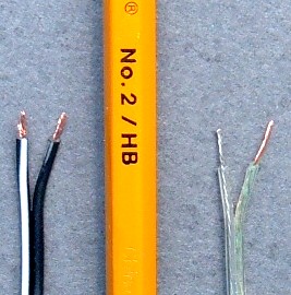
The transformer and its six-foot cord will seldom be long enough to reach the display unit from a power outlet, and will need to be extended. This is done with a small-gauge two-conductor zip cord and two tiny wire nuts. This cord connects between the display unit and the transformer cord--not to an AC outlet!
The transformer has a somewhat stiff cord, a hair dryer can be used to soften and unkink the cord just prior to installation.
Wall transformer cords are often made with 24-gauge wires. When extending the cord, a similar gauge wire (20, 22, or 24) should be used, otherwise it can be difficult to wire-nut the small cord wires to much larger wires. The smaller the extension wires are, the easier and better-looking the installation will be. Speaker wire is available in these gauges. There is no practical limit to the length of the extension. 100, even 200 feet is not too long.
Drill a hole in the sliding backpanel
for the extension wire
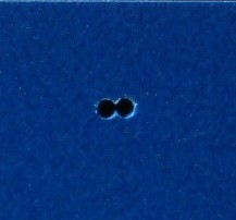
If the extension wire has to pass through a wall, a 3/16" hole should be large enough to accept the wires. A long drill bit may be required. Usually there is an inner and outer wall separated by air or insulation. In this case, a piece of coat hanger can be joined to the wire end with duct tape and drawn through the wall hole.
To wire the LEDress, drill a hole in the sliding back-panel of the display enclosure. The hole should be near the center of the panel so that it can be slid to the right, exposing the terminal block, and to the left, exposing the display mode jumpers. If the wire enters the panel on one end, the panel can not be slid far enough in that direction to access the terminals or jumpers. The picture shows two overlapping holes that match the shape of the cord, but one hole works just as well.
After wiring, seal the LEDress enclosure hole containing the wire. Otherwise, water or snowmelt will run down the wire in an unsealed hole and pool on the circuit board inside.
Sliding backpanel with extension wire
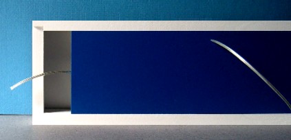
Feed the wire through the back-panel into the enclosure. Feed plenty of wire in--a foot or more is not too much. Then when the panel is slid to the right, the wire inside can be reached.
Wiring to the terminal block
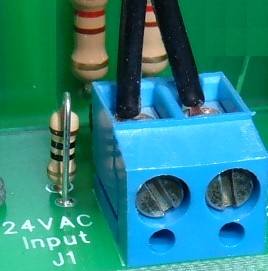
Separate up to 1 1/2" of the two conductors using very small scissors or a pen knife. Remove a short piece of insulation from each wire, and connect the wires to the terminal block, tightening with a small screwdriver. It may help to fold the bare wire portion in half, making it thicker so that the terminal block grips it better. There is no polarity--the wires can be connected in any order. Leave plenty of slack wire inside the enclosure so that the panel can be slid back and forth without tugging the wires.
Insert the wires into the top of the terminal block; do not use the little front holes below the screws!
Matched cord sizes and small wire nuts
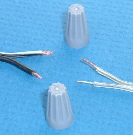
The transformer wires and extension wires can be routed using "low voltage staples" or other insulated staples. See the Hardware link for more details. Remove some insulation from all wires and join the two cords with wire nuts. One wire from each cord goes in one nut, and the two remaining wires go into the other nut. Use very small wire nuts so that the wires will be reliably connected. See the beginner's section below on how to make good wire nut connections.
Unwired and wired vertical unit
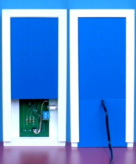
The vertical units are shipped with a split backpanel; the bottom portion slides down and is notched to accomodate wires.
Below here is the beginner's section for those with no wiring experience
Inserting and tightening the wires
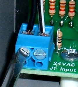
Separate up to 1 1/2" of the two conductors using very small scissors or a pen knife. Remove some insulation from the ends of both wires using a wire stripper. 3/16" to 1/4" of removed insulation is ideal. A craft or utility knife may be used instead by placing the blade on top of the wire and rolling the wire back and forth. The main idea is to not cut into the wire. If more than one or two tiny strands of wire fall off, or remain inside the pulled-off bit of insulation, cut the whole bare portion off and start again.
If too little insulation is removed, the terminal block may clamp down on the insulation instead and not make contact with the bare wire.
Keep the length of both wires and the length of insulation removed on each wire the same. The wires can be connected in any order, there is no polarity.
Twist the bare wires a bit so they do not have any frayed strands. Insert each wire into a terminal block receptacle with one hand and tighten the screws with the other hand. Tighten firmly but do not bear down. Then tug on the wires a little to make sure they are held fast.
It is best to use a flat screwdriver with a 1/8" blade.
To remove the wires, loosen the screws first rather than yanking the wires out forcibly.
Do not put the wires here!!
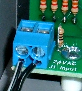
Although these holes look inviting, they are not intended for wires. Besides, the backpanel slides right past here.
Too much insulation was removed
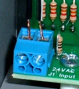
If too much insulation is removed from the wires, the bare wires may touch or short out when the power cord is moved sideways when the backpanel is slid shut. Even a large change in temperature could cause the wires to move and touch.
Your wiring should look like this
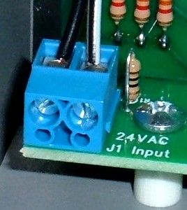
This is an example of a tidy wiring job, no insulation is inside the terminal block and no excess bare wire is outside the terminals.
Prepared wires
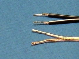
The wires first need to be separated for about 1 1/2", use a sharp knife and cut right down the middle without cutting into the bare wire itself. Then the ideal amount of insulation to remove from the wires is 1/2". Wire strippers are typically used, but careful use of the knife is possible. Keeping each separated wire length and each bared wire length equal will make the nutting process easier.
Folded wires
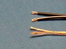
Since the wires are so small (24-gauge), the easiest method to get a good connection is to fold the bared 1/2" wire ends in half, forming a 1/4" bare wire stub that has twice the diameter. The transformer wires are already bared about 1/2", just fold that part in half. You can accomplish the same thing by not folding first, but twist the bare part of one transformer and of one extension wire together, and fold the whole twisted bare part in half. Repeat with the other two remaining wires.
Wire nut setup
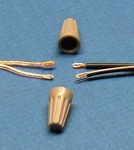
Insert one transformer wire and one extension wire into each nut and twist the nut three to five times until a slight tug will not remove the wires from the nut. Too much twisting may break the wires. Too little twisting may allow the wire nut to fall off.
After inserting and before twisting, grip the two wires with thumb and index finger very close to the wire nut.
If you try to put one unfolded transformer wire and one unfolded extension wire in the nut, it may not grip the bare wire properly, unless you have found some very tiny wire nuts for 24-gauge wire.
There is no polarity when powering from an AC transformer; that is, the wires can be connected in any order, the white stripe or bare wire color does not matter.
Finished wire nut result
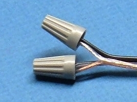
The final wire-nutting should look like this. The bared wires are twisted together inside the little metal cone of the wire nut and the insulated wire is in the plastic part of the wire nut--no bare wire shows outside of the nut.


